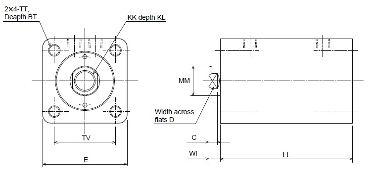
160S-1/THS16 Bore |
SD |
General purpose type |
160S-1 6 SD Bore N Stroke T (ø20 - ø125) |
Cutting fluid proof type |
160SW-1 6 SD Bore N Stroke T (ø32 - ø100) |
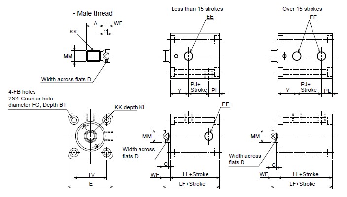
None : Female thread
T: Male thread |
|
&S226; Bore ø20, ø25 |
|
&S226; Bore ø32 - ø125 |
|
Dimension Table |
Symbol
Bore |
A |
AE |
BT |
C |
D |
DE |
E |
EE |
FB |
FF |
FG |
KK |
KL |
Female thread |
Male thread |
ø20 |
15(25) |
– |
5.4 |
6 |
10 |
– |
44 |
Rc1/8 |
ø5.5 |
– |
ø9.5 |
M8&<0005;1.25 |
M10&<0005;1.25 |
10 |
ø25 |
18(30) |
– |
5.4 |
6 |
12 |
– |
50 |
Rc1/8 |
ø5.5 |
– |
ø9.5 |
M10&<0005;1.5 |
M12&<0005;1.25 |
12 |
ø32 |
25(40) |
8 |
6.5 |
7 |
14 |
ø17.5 |
62 |
Rc1/4 |
ø6.6 |
G1/8 |
ø11 |
M12&<0005;1.75 |
M16&<0005;1.5 |
15 |
ø40 |
30(45) |
8 |
8.6 |
7 |
19 |
ø17.5 |
70 |
Rc1/4 |
ø9 |
G1/8 |
ø14 |
M16&<0005;2 |
M20&<0005;1.5 |
20 |
ø50 |
35(50) |
12 |
10.8 |
8 |
24 |
ø21.5 |
80 |
Rc1/4 |
ø11 |
G1/4 |
ø17.5 |
M20&<0005;2.5 |
M24&<0005;1.5 |
24 |
ø63 |
45(60) |
12 |
13 |
9 |
30 |
ø21.5 |
94 |
Rc1/4 |
ø14 |
G1/4 |
ø20 |
M27&<0005;3 |
M30&<0005;1.5 |
33 |
ø80 |
60(80) |
12 |
15.2 |
14 |
41 |
ø21.5 |
114 |
Rc3/8 |
ø16 |
G1/4 |
ø23 |
M30&<0005;3.5 |
M39&<0005;1.5 |
36 |
ø100 |
75(95) |
12 |
19.5 |
22 |
50 |
ø25.5 |
140 |
Rc3/8 |
ø20 |
G3/8 |
ø29 |
M39&<0005;4 |
M48&<0005;1.5 |
45 |
ø125 |
95(125) |
14 |
23.5 |
25 |
65 |
ø30 |
172 |
Rc1/2 |
ø24 |
G1/2 |
ø35 |
M48&<0005;5 |
M64&<0005;2 |
58 |
|
|
Symbol
Bore |
LF |
LL |
MM |
N |
PJ |
PL |
TV |
WF |
Y |
Rc thread |
G thread |
Rc thread |
G thread |
Rc thread |
G thread |
Rc thread |
G thread |
ø20 |
51 |
43 |
ø12 |
– |
– |
10.5 |
– |
12 |
– |
30 |
8 |
20.5 |
– |
ø25 |
53 |
45 |
ø14 |
– |
– |
12.5 |
– |
12 |
– |
36 |
8 |
20.5 |
– |
ø32 |
64 |
54 |
ø18 |
10 |
10 |
14 |
14 |
12 |
12 |
47 |
10 |
28 |
28 |
ø40 |
65 |
55 |
ø22 |
10 |
10 |
16 |
16 |
12 |
12 |
52 |
10 |
27 |
27 |
ø50 |
71 |
60 |
ø28 |
10 |
14 |
19 |
13.5 |
13 |
18.5 |
58 |
11 |
28 |
28 |
ø63 |
80 |
67 |
ø36 |
10 |
16 |
24 |
20 |
13 |
17 |
69 |
13 |
30 |
30 |
ø80 |
95 |
78 |
ø45 |
15 |
19 |
25 |
24 |
18 |
18 |
86 |
17 |
35 |
36 |
ø100 |
122 |
96 |
ø56 |
15 |
18 |
26 |
26 |
28 |
28 |
106 |
26 |
42 |
42 |
|
Notes) &S226; When you use the cylinder with lock nut, we recommend you change A dimension for parenthetic one.
&S226;The lock nut needs to be ordered separately.
&S226;20mm and 25mm bore size of Cutting Fluid Proof Type are not available.
&S226;Allowance of MM is f8. |
|
ST |
General purpose type |
160S-1 6 ST Bore N Stroke T (ø32 -ø80/Made-to-order) |
None : Female thread
T : Male thread |
over 101 strokes (110,120,130,140,150,160,170,180,190,200? |
|
&S226; Bore ø32 -ø80 |
|
|
Dimension Table |
Symbol
Bore |
A |
BT |
C |
D |
E |
EE |
KK |
MM |
N |
TT |
TV |
WF |
Y |
Female thread |
Male thread |
ø32 |
25(40) |
15 |
7 |
14 |
62 |
Rc1/4 |
M12&<0005;1.75 |
M16&<0005;1.5 |
ø18 |
10 |
M6&<0005;1 |
47 |
10 |
28 |
ø40 |
30(45) |
20 |
7 |
19 |
70 |
Rc1/4 |
M16&<0005;2 |
M20&<0005;1.5 |
ø22 |
10 |
M8&<0005;1.25 |
52 |
10 |
27 |
ø50 |
35(50) |
25 |
8 |
24 |
80 |
Rc1/4 |
M20&<0005;2.5 |
M24&<0005;1.5 |
ø28 |
10 |
M10&<0005;1.5 |
58 |
11 |
28 |
ø63 |
45(60) |
30 |
9 |
30 |
94 |
Rc1/4 |
M27&<0005;3 |
M30&<0005;1.5 |
ø36 |
10 |
M12&<0005;1.75 |
69 |
13 |
30 |
ø80 |
60(80) |
35 |
14 |
41 |
114 |
Rc3/8 |
M30&<0005;3.5 |
M39&<0005;1.5 |
ø45 |
15 |
M16&<0005;2 |
86 |
17 |
35 |
|
|
Symbol
Stroke
Bore |
LL |
PJ |
110 |
120 |
130 |
140 |
150 |
160 |
170 |
180 |
190 |
200 |
110 |
120 |
130 |
140 |
150 |
160 |
170 |
180 |
190 |
200 |
ø32 |
192 |
202 |
212 |
222 |
232 |
242 |
252 |
262 |
272 |
282 |
136 |
146 |
156 |
166 |
176 |
186 |
196 |
206 |
216 |
226 |
ø40 |
192 |
202 |
212 |
222 |
232 |
242 |
252 |
262 |
272 |
282 |
138 |
148 |
158 |
168 |
178 |
188 |
198 |
208 |
218 |
228 |
ø50 |
195 |
205 |
215 |
225 |
235 |
245 |
255 |
265 |
275 |
285 |
139 |
149 |
159 |
169 |
179 |
189 |
199 |
209 |
219 |
229 |
ø63 |
202 |
212 |
222 |
232 |
242 |
252 |
262 |
272 |
282 |
292 |
142 |
152 |
162 |
272 |
182 |
192 |
202 |
212 |
222 |
232 |
ø80 |
215 |
225 |
235 |
245 |
255 |
265 |
275 |
285 |
295 |
305 |
145 |
155 |
165 |
175 |
185 |
195 |
205 |
215 |
225 |
235 |
|
Notes) &S226; When you use the cylinder with lock nut, we recommend you change A dimension for parenthetic one.
&S226; The lock nut needs to be ordered separately.
&S226; Allowance of MM is f8. |
|
160S-1/THS16 Bore |
LA |
General purpose type160S-1 6 LA Bore N Stroke T (ø32 -ø63) |
None : Female thread
T: Male thread |
|
&S226; Bore ø32 -ø63 |
|
Dimension Table |
Symbol
Bore |
A |
BT |
C |
D |
EA |
EB |
EE |
FG |
GB |
KK |
KL |
LF |
LH |
Female thread |
Male thread |
ø32 |
25(40) |
8.6 |
7 |
14 |
70 |
56 |
Rc1/4 |
ø14 |
ø9 |
M12&<0005;1.75 |
M16&<0005;1.5 |
15 |
64 |
25±0.06 |
ø40 |
30(45) |
10.8 |
7 |
19 |
80 |
64 |
Rc1/4 |
ø17.5 |
ø11 |
M16&<0005;2 |
M20&<0005;1.5 |
20 |
65 |
29±0.06 |
ø50 |
35(50) |
13 |
8 |
24 |
94 |
74 |
Rc1/4 |
ø20 |
ø14 |
M20&<0005;2.5 |
M24&<0005;1.5 |
24 |
71 |
34±0.06 |
ø63 |
45(60) |
15.2 |
9 |
30 |
114 |
89 |
Rc1/4 |
ø23 |
ø16 |
M27&<0005;3 |
M30&<0005;1.5 |
33 |
80 |
42±0.06 |
|
|
Symbol
Bore |
LL |
MM |
N |
PJ |
PL |
SG |
SW |
SY |
T |
TS |
TW |
TX |
TZ |
WF |
Y |
ø32 |
54 |
ø18 |
10 |
14 |
12 |
24 |
10 |
20 |
63 |
56 |
12 |
28 |
14 |
10 |
28 |
ø40 |
55 |
ø22 |
10 |
16 |
12 |
23 |
12 |
20 |
70 |
62 |
12 |
28 |
15 |
10 |
27 |
ø50 |
60 |
ø28 |
10 |
19 |
13 |
27 |
13 |
20 |
80 |
74 |
14 |
29 |
17 |
11 |
28 |
ø63 |
67 |
ø36 |
10 |
24 |
13 |
32 |
15 |
20 |
100 |
90 |
16 |
31 |
20 |
13 |
30 |
|
Notes) &S226; When you use the cylinder with lock nut, we recommend you change A dimension for parenthetic one.
&S226; The lock nut needs to be ordered separately.
&S226; Allowance of MM is f8. |
|
Recommended Key Way Dimensions |
When using a parallel key: |
|
|
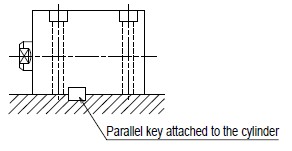
When not using a parallel key: |
|
Dimension Table |
Use the same dimensions for the stopper as the attached parallel key. |
Bore |
Key’s Nominal Dimensions
b &<0005; h &<0005; 1 |
Key Way Dimensions
|
b1 |
t1 |
r1 |
ø32 |
12&<0005;8&<0005;63 (Both rounded) |
12 0 –0.043 |
5 +0.2 0 |
0.25 - 0.40 |
ø40 |
12&<0005;8&<0005;70 (Both rounded) |
12 0 –0.043 |
5 +0.2 0 |
ø50 |
14&<0005;9&<0005;80 (Both rounded) |
14 0 –0.043 |
5.5 +0.2 0 |
ø63 |
16&<0005;10&<0005;100 (Both rounded) |
16 0 –0.043 |
6 +0.2 0 |
|
&S226; When using the foot type, use the attached parallel key to install the cylinder, referring to the “Recommended Key Way Dimensions.”
&S226; When not using the parallel key, attach the stoppers to the cylinder’s front and rear sides toward its stroke direction. If the cylinder is used without using the key or stoppers, a large force is applied to the cylinder’s mounting bolts, possibly resulting in the fracturing of the bolts. |
|


 &S226; Bore ø32 - ø125
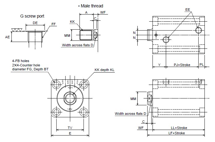 Dimension TableSymbol
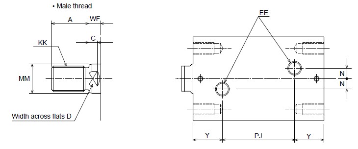
 Dimension TableSymbol
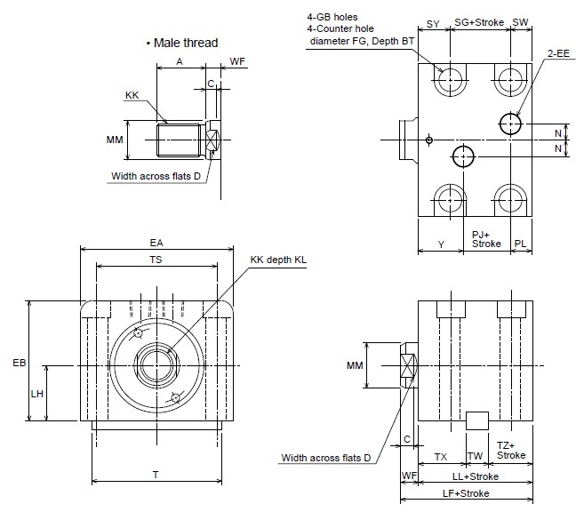 Dimension TableSymbol
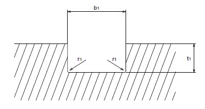
 When not using a parallel key:
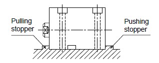 Dimension TableUse the same dimensions for the stopper as the attached parallel key.BoreKey’s Nominal Dimensions


